
Choosing the right Safety Lockout devices starts with understanding the equipment, energy sources, and tasks involved. A padlock may secure a simple electrical isolator, while a valve, plug, or cable may need a dedicated device. The right fit matters. A lock that slips from a switch handle or leaves a valve partly accessible can undermine the control you intended to create. Small details count, such as handle shape, available clearance, and whether several workers need to apply personal locks.
A practical selection process begins with observing the machine and checking its energy-isolating points. Record what each point controls, how it is operated, and what device can hold it securely in the isolated position. Then consider durability, visibility, labeling, and compatibility with the site’s established lockout procedures. For example, a busy workshop may need brightly colored devices that remain easy to identify beside oily equipment. Manufacturer instructions and input from qualified safety personnel can help confirm that a device suits its intended application. Fit should be verified. A catalog description alone cannot prove that a device works on a particular machine.
There is no single device for every hazard. Some choices become clearer only after a hands-on review, and that review may expose gaps in existing procedures. Be willing to reconsider. This guide outlines the key questions to ask when comparing lockout devices, from identifying energy sources to checking fit and routine use. The goal is not to buy the largest kit. It is to select equipment that workers can apply correctly, recognize quickly, and maintain consistently.
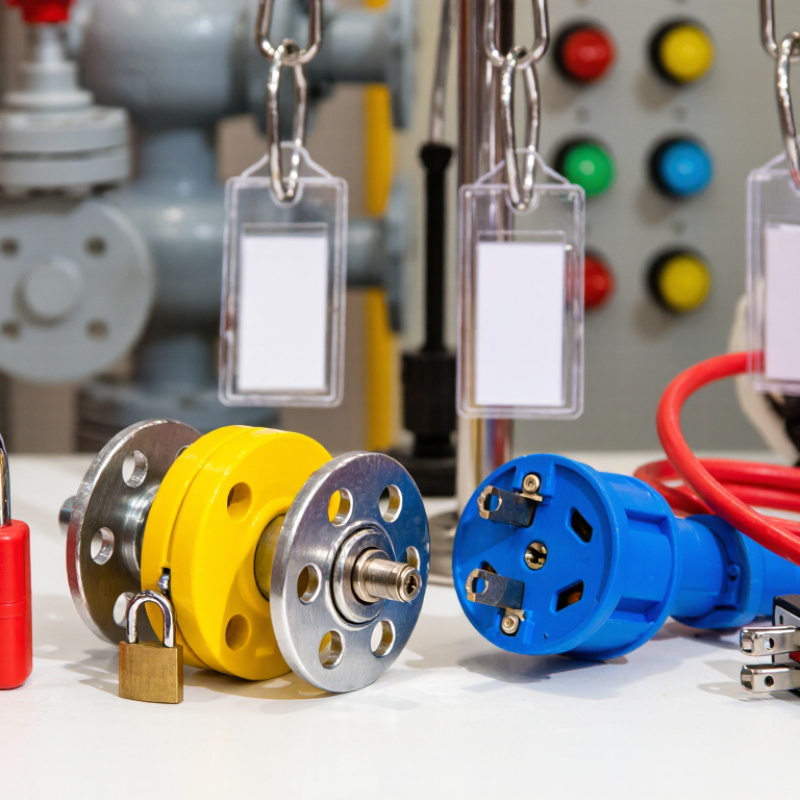
Safety lockout devices create a physical barrier between workers and hazardous energy. A padlock, valve cover, or circuit-breaker lock keeps equipment from being switched on during servicing. Tags identify the person responsible and warn others not to operate the equipment. The purpose is direct: prevent unexpected startup or energy release while someone works near moving parts, electricity, pressure, or heat. OSHA estimates that effective compliance with its lockout/tagout standard prevents 120 fatalities and 50,000 injuries each year. This figure appears in OSHA’s Control of Hazardous Energy overview. It is an estimate, not a guarantee.
Selecting a device starts with the machine’s energy sources and isolation points. A breaker lock must fit the switch; a valve cover must stop the handle from turning. Some machines need several locks because they use more than one energy source. Check fit, durability, visibility, and whether workers can apply the device without awkward reaches. The Bureau of Labor Statistics recorded 2.6 million nonfatal workplace injury and illness cases in private industry in 2023. That broad figure is not specific to lockout incidents, but it shows why prevention matters. Real workshops are less tidy than diagrams. A device that looks suitable on paper may not fit a worn or crowded control panel, so verify it on the actual equipment.

Follow the lockout/tagout sequence, then choose devices that fit the specific energy-isolating points on your equipment.
How to use this chart: The bar heights show the sequence of steps, not time or risk. Select a lockout device that physically fits and securely holds the isolating device in the safe position. Devices should be durable, standardized, substantial, and identifiable. Always account for stored energy and verify isolation before work begins.
Before selecting a safety lockout device, identify every energy source that can move, heat, pressurize, or energize the equipment. A conveyor may have an electrical disconnect, pneumatic actuators, and a raised section held by gravity. One switch rarely tells the whole story. Trace cables, air lines, hydraulic hoses, and connected equipment. Check machine drawings against what is physically installed; drawings can be outdated.
Mark each isolation point clearly and note what it controls. A wall-mounted disconnect may isolate the motor but leave a separate control circuit live. A valve may stop incoming air while pressure remains trapped downstream. Look for capacitors, springs, elevated loads, hot surfaces, and pressure accumulators. The machine is quiet. That is not proof of safety. Choose devices that fit the actual point, such as a breaker lockout, valve lockout, or cable device, and confirm they cannot be removed without authorization.
After isolating energy, follow the site procedure to release or restrain stored energy and verify the equipment cannot start. Qualified workers should use suitable test methods for electrical circuits and check pressure gauges where relevant. A zero reading can be misleading if the gauge is faulty, so consider an independent check when the risk warrants it. Record unusual feeds or unclear points for review. The map is rarely perfect on day one, and that deserves a second look.
| Hazardous Energy Source | Typical Lockout Point | Common Lockout Device | Key Selection Considerations | Energy Isolation Check |
|---|---|---|---|---|
| Electrical energy | Disconnect switch, circuit breaker, or other designated isolating device | Electrical lockout device compatible with the isolator, plus a personal safety padlock and tag | Confirm the device fits the specific switch or breaker and prevents operation. Follow the site procedure for identifying all electrical supplies. | A qualified person verifies absence of voltage with suitable test equipment after isolation and before work begins. |
| Plug-connected electrical equipment | Power plug or receptacle connection | Plug lockout enclosure sized for the plug, secured with a personal safety padlock | Check that the enclosure fully contains the plug and cannot be removed while locked. Where required by the procedure, the plug must remain under the exclusive control of the worker. | Confirm the equipment cannot be energized and verify that stored electrical energy has been addressed. |
| Pneumatic energy | Compressed-air supply valve or designated isolation point | Valve lockout device appropriate to the valve, with a personal safety padlock and tag | Identify the correct supply valve and account for downstream pressure, accumulators, and any secondary air feeds. | Isolate the supply, release trapped pressure using the approved method, and verify that pressure is relieved. |
| Hydraulic energy | Hydraulic supply valve, pump disconnect, or designated isolation point | Compatible valve lockout device; additional blocking or restraint may be needed for moving parts | Consider pressure trapped in lines or accumulators and loads that could move when pressure is removed. Do not rely on a control valve alone if it does not isolate the energy source. | Relieve pressure as specified, check for stored energy, and secure components that could fall or move. |
| Mechanical or gravitational energy | Moving parts, raised equipment, counterweights, or suspended loads | Purpose-designed blocking, pins, or restraints; lockable isolators for any driving power source | Select a restraint rated and positioned for the load and expected forces. A lock on an energy switch does not by itself prevent gravity-driven movement. | Lower equipment where possible, or install and inspect suitable blocks or restraints before entering the hazard area. |
| Thermal energy | Steam, hot-fluid, or heating-system isolation valve; equipment power isolator where applicable | Compatible valve lockout device and personal safety padlock; use additional isolation where the procedure requires it | Identify supply and return lines, bypasses, and possible heat sources. Allow for cooling time and the risk of pressure or hot material remaining in the system. | Verify isolation and confirm the equipment or material has reached a safe condition using the site procedure. |
| Chemical or process energy | Process-line isolation valve, tank inlet, or other designated supply point | Valve lockout device and tag; additional measures such as line blanking may be required by the procedure | Check the substance, line configuration, possible cross-connections, and whether a closed valve provides adequate isolation for the task. | Drain, flush, purge, or test the system as required by the chemical hazard assessment and site procedure. |
Important: Device selection must match the actual isolating point and the equipment-specific energy-control procedure. Identify every energy source, apply each worker’s required lock and tag, control stored energy, and verify isolation before work begins.
How to Choose the Right Safety Lockout Devices?
Matching Device Types to Equipment and Energy Sources
Choose a lockout device that matches the equipment’s isolation point, not just its general energy type. Start by identifying every source: electrical, mechanical, hydraulic, pneumatic, or thermal. A breaker lockout should fit the breaker handle securely and prevent movement. For plug-connected equipment, a plug cover can enclose the plug and keep it out of the socket. Fit matters. Check that the device cannot be removed or bypassed while the lock is applied.
Valves need devices suited to their shape and operation. A gate valve may require a wheel cover, while a ball valve may need a clamp that holds its handle closed. For air lines, use a pneumatic lockout designed for the connector; trapped pressure may still move a cylinder. Stored energy matters, too. A blocked machine part or charged capacitor can remain hazardous after isolation. A common miss is locking the supply but overlooking residual energy.
For equipment with several isolation points, a group lockbox can help each worker apply a personal lock after the sources are secured. On awkward machinery, an adjustable cable device may cover multiple points, but only when it holds them reliably. Check device fit, material, and operating conditions against the equipment and site procedure. Then verify isolation before work begins. A label helps identify the point, but it cannot replace a physical lock or a careful check.
How to Choose the Right Safety Lockout Devices?
Workplace conditions and regulatory requirements should guide device selection. Walk the actual work area before making a list. A damp washdown room may need corrosion-resistant equipment, while a cramped cabinet may require compact hasps. Check each energy source, including electrical, hydraulic, pneumatic, and stored mechanical energy. A machine can have more than one.
Review the equipment’s isolation points and your written procedures. Devices must fit the valves, switches, and plugs workers actually use. Check applicable regulations and industry standards for your location, and confirm requirements with a qualified safety professional. Rules and interpretations can change. A checklist helps, but it may miss a hard-to-reach disconnect or an unusual maintenance task.
Tips: Test device fit on site. Ask maintenance staff to demonstrate isolation. Include contractors and shift handoffs in the review. If a device blocks access or is awkward with gloves, workers may be tempted to work around it. That is worth treating as a design problem, not just a training issue. Revisit the selection after equipment changes or near misses. Some workplaces discover gaps only during a real shutdown, which is not ideal—but useful feedback should still update the procedure.
How to Choose the Right Safety Lockout Devices?
Compatibility begins at the machine, not the catalog. Check the energy source, isolation point, and device dimensions before purchase. A breaker clip must fit securely, while a valve cover must fully block handle movement. Also confirm shackle clearance, material compatibility, and whether several workers need to attach locks. A device that almost fits is still a mismatch.
Durability matters in real work areas. Oil, moisture, metal shavings, sunlight, and temperature swings can wear devices or make them hard to operate. Choose materials suited to those conditions, then inspect for cracks, corrosion, loose parts, and faded identification. OSHA’s 29 CFR 1910.147 requires periodic inspections of energy-control procedures at least annually. OSHA also estimates that effective lockout/tagout can prevent 120 fatalities and 50,000 injuries each year. The figures are estimates, but they underline why fit and upkeep deserve attention.
Tips: Test each device at the isolation point before relying on it. Keep a simple inspection log, and replace damaged units promptly. A checklist can miss a subtle fit problem; hands-on checks help catch it. Don’t forget spare keys, labels, and storage conditions.
Contact
KYOCERA SGS Precision Tools, Inc.
(330) 686-5700
150 Marc Drive
Cuyahoga Falls, OH 44223
Products
Resources