
Choosing the right Optical Attenuator can determine whether a fiber link performs smoothly or fails during testing. The device may look small, but its specifications influence signal stability, receiver protection, and measurement accuracy. A fixed attenuator may suit a stable network, while a variable model offers finer control during commissioning. The wrong choice can create hidden losses.
Optical communications expert Dr. Alan E. Willner has emphasized, “Reliable optical systems depend on precise control of light.” That principle guides every decision in this guide. Wavelength range matters because an attenuator designed for 850 nanometers may not perform equally at 1310 or 1550 nanometers. Connector type matters too. A dusty LC connector can distort results before the attenuator even enters the test.
The ten tips examine attenuation value, insertion loss, return loss, power handling, calibration, and operating environment. They also consider polarization sensitivity and long-term stability. Check the datasheet carefully. Numbers can be misleading without test conditions. A laboratory-grade attenuator may be excessive for a basic link, while a low-cost unit may drift under heat.
Real installations are rarely perfect. Cables bend, connectors age, and technicians sometimes trust labels too quickly. I have seen a small mismatch waste an entire afternoon of testing. That mistake is easy to repeat. Careful selection, clean connections, and measured verification provide a more dependable path. The best Optical Attenuator is not simply the cheapest or strongest model. It is the one that matches the wavelength, power level, connector system, and actual working conditions.
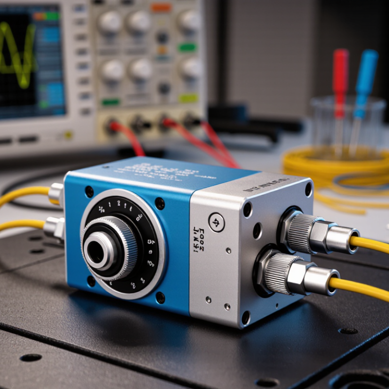
An optical attenuator reduces light power without changing the signal path. It helps receivers operate within their safe input range. Fixed attenuators provide one stable loss value. Variable attenuators allow controlled adjustment during testing and commissioning. The correct choice depends on wavelength, attenuation range, connector type, and optical mode. Check insertion loss carefully. Extra loss can distort a tight power budget.
In telecommunications, attenuators balance channels and prevent receiver overload. Test engineers use them to simulate long fiber spans on a short bench. They also support transceiver measurements, sensor calibration, and laboratory fault checks. Return loss matters when reflections may disturb sensitive equipment. Power handling matters too. A device rated for low power may fail in a high-power link. Polarization-dependent loss can also affect precision systems, especially during measurement.
Small details often decide performance. Clean every connector before testing. Confirm the operating wavelength, then verify the actual loss with a calibrated power meter. Match connector polish and fiber type. Consider temperature stability for outdoor or industrial installations. Check whether the attenuator supports the required adjustment resolution. Keep a spare adapter nearby. It helps.
A practical mistake is choosing attenuation from a nominal power value alone. Real transmitters fluctuate, connectors age, and meters have uncertainty. I have seen a suitable attenuator perform poorly because a connector was contaminated. That result was inconvenient, but useful.
Recheck the entire link, not only the component. A final inspection of power, reflection, and stability usually reveals the real problem.

10 Tips for Choosing the Right Optical Attenuator
Matching attenuation to system power starts with a simple power budget. Measure the transmitter output at the actual operating wavelength, then subtract fiber and connector losses. The remaining power must fit within the receiver’s specified input range. Use the formula: output power equals input power minus attenuation. Do not rely only on nominal transmitter values. Field measurements can reveal unexpected peaks. A receiver exposed to excessive power may saturate, while excessive attenuation can reduce signal quality and increase errors.
Tip: Check average and peak power separately. Select an attenuator with a rating above the highest measured level, not merely the typical level. Leave a practical safety margin, often 1–3 dB, but confirm the receiver’s exact limits. Fixed attenuation suits stable links. Variable attenuation is more flexible during testing, though its adjustment scale can introduce mistakes.
Tip: Match wavelength, connector type, return loss, and attenuation tolerance. A device rated for one wavelength may perform differently across a broad spectrum. Clean every connector before testing. Small particles can change readings and damage interfaces. I have found that engineers sometimes choose a convenient attenuation value first, then adjust the calculation afterward. That approach feels efficient, but it can hide a weak power budget. Recheck the link after installation, especially when temperature, cable routing, or transmit settings change. A second measurement is rarely wasted.
The chart shows the minimum attenuation required to reduce different optical input-power levels to a 1 mW receiver limit. Attenuation is calculated as A(dB) = 10 × log10(Input Power / Target Power).
Select an attenuator with a rated value equal to or slightly above the calculated requirement, while confirming its operating wavelength, power-handling capability, connector type, and insertion-loss tolerance.
Choosing the right optical attenuator starts with understanding how your test will change. Fixed attenuators provide a stable loss value, such as 3 dB or 10 dB. They are simple, repeatable, and useful for protecting receivers from excessive optical power. Their compact design also reduces setup errors. However, a fixed unit cannot follow changing signal conditions.
Variable attenuators offer manual control through a dial or adjustment screw. They suit laboratory measurements, where engineers may tune power while checking sensitivity or insertion loss. Watch the adjustment range carefully. A broad range is helpful, but it may reduce resolution near the level you need. Programmable attenuators add remote control, stored settings, and automated test sequences. They are valuable in production systems and long measurement runs, although software delays and communication failures can complicate troubleshooting. I once assumed automation would remove every inconsistency. It did not; calibration and connector cleanliness still mattered more than expected.
Check wavelength range, maximum input power, return loss, connector type, and calibration uncertainty before ordering. A device rated for one optical band may perform poorly in another. Also inspect the attenuation accuracy at both low and high settings. For field work, fixed attenuation is often the safer choice. For changing experiments, variable control gives better flexibility. Programmable models make sense when repeatability, logging, and remote operation justify their added complexity. Do not overlook the operator. A technically advanced attenuator can create avoidable mistakes when its interface is unclear.
Choosing an optical attenuator starts with the operating wavelength. A unit designed for 1310 nm may not perform accurately at 1550 nm. Check the specified wavelength range, attenuation accuracy, and power rating together. A wide range is useful, but it does not guarantee equal performance across every wavelength. I have learned to compare test conditions, not only headline figures.
Connector selection deserves the same attention. Match the connector type, polish style, and fiber mode with the existing link. A clean connector face matters. Dust can increase loss and create unstable readings. APC and UPC interfaces should not be mixed casually. They may connect physically, but their optical performance can suffer. Verify keying and adapter compatibility before installation.
Insertion loss is another specification that is easy to overlook. The attenuator should provide the intended attenuation without adding excessive extra loss. Ask whether the stated value includes connector loss, and check the measurement tolerance. A small error can affect a tight power budget. Test the component with calibrated equipment at the real operating wavelength. Do not trust appearance alone. The housing may look precise while the specification leaves important details unclear. When figures seem incomplete, request a full test report and record the conditions used.
Choosing an optical attenuator begins with its accuracy, not its lowest price. Check the stated attenuation range, insertion loss, and calibration uncertainty. A device marked “precise” may still drift under heat. Measure performance at the wavelengths your system actually uses. Laboratory experience shows that repeatability matters as much as initial accuracy. Test the setting several times. Small errors can affect receiver sensitivity results.
Reliability depends on construction and operating conditions. Review maximum optical power, connector quality, adjustment life, and temperature stability. A field unit may face dust, vibration, and frequent handling. Ask for calibration records and clear test methods. Traceable documentation strengthens technical decisions. Still, paperwork cannot replace practical testing. I once trusted a specification sheet too quickly. The connector fit was correct, but the measured loss changed after repeated use.
Compatibility requires more than matching connector names. Confirm fiber type, wavelength range, polarization behavior, and interface geometry. Check whether the attenuator fits your power meter and test setup without extra adapters. Adapters add cost and possible loss. Compare the purchase price with calibration, replacement, shipping, and downtime expenses. The cheapest option may become expensive after one failed measurement. A higher initial cost can be sensible when stability, serviceability, and documented performance reduce future risk. Keep the calculation realistic. Tests rarely happen under perfect conditions.
Contact
KYOCERA SGS Precision Tools, Inc.
(330) 686-5700
150 Marc Drive
Cuyahoga Falls, OH 44223
Products
Resources