Why Choose an Extruded Heat Sink?
Why Choose an Extruded Heat Sink?
Electronic devices are becoming smaller, faster, and more thermally demanding. Their heat does not disappear. It moves through materials, interfaces, fins, and surrounding air. An Extruded Heat Sink offers a practical path for managing that movement.
Grand View Research’s 2024 heat-sink market analysis identifies rising power density and electronics miniaturization as major industry drivers. The U.S. Department of Energy’s Solid-State Lighting R&D reports also emphasize thermal management as a key factor in LED performance and lifetime. These findings support a simple engineering reality: cooling cannot be treated as an afterthought.
Extrusion creates continuous aluminum profiles with consistent fins and reliable dimensional control. Manufacturers can cut one profile into many lengths. This reduces tooling complexity and supports repeatable production. Aluminum alloys also provide useful thermal conductivity, low weight, and corrosion resistance. In a server chassis, the result may be a finned profile pressed against a hot processor. In an LED luminaire, it may become the entire rear housing.
Thermal engineer Dr. Satish Kandlikar has said, “Effective cooling depends on managing the complete thermal path.” That principle matters here. A large heat sink cannot compensate for poor contact pressure, uneven thermal paste, blocked airflow, or an undersized enclosure.
The choice is not automatic.
A larger profile is not always better. It may increase cost, weight, and airflow resistance. Product teams should compare junction temperature, pressure drop, surface area, alloy, mounting method, and production volume. Some design assumptions will be wrong. Testing with thermocouples or infrared imaging remains essential. An Extruded Heat Sink succeeds when its geometry matches the real application, not merely the specification sheet.
Define Extruded Heat Sinks: 6063 Aluminum Conducts About 200 W/m·K
Why Choose an Extruded Heat Sink?
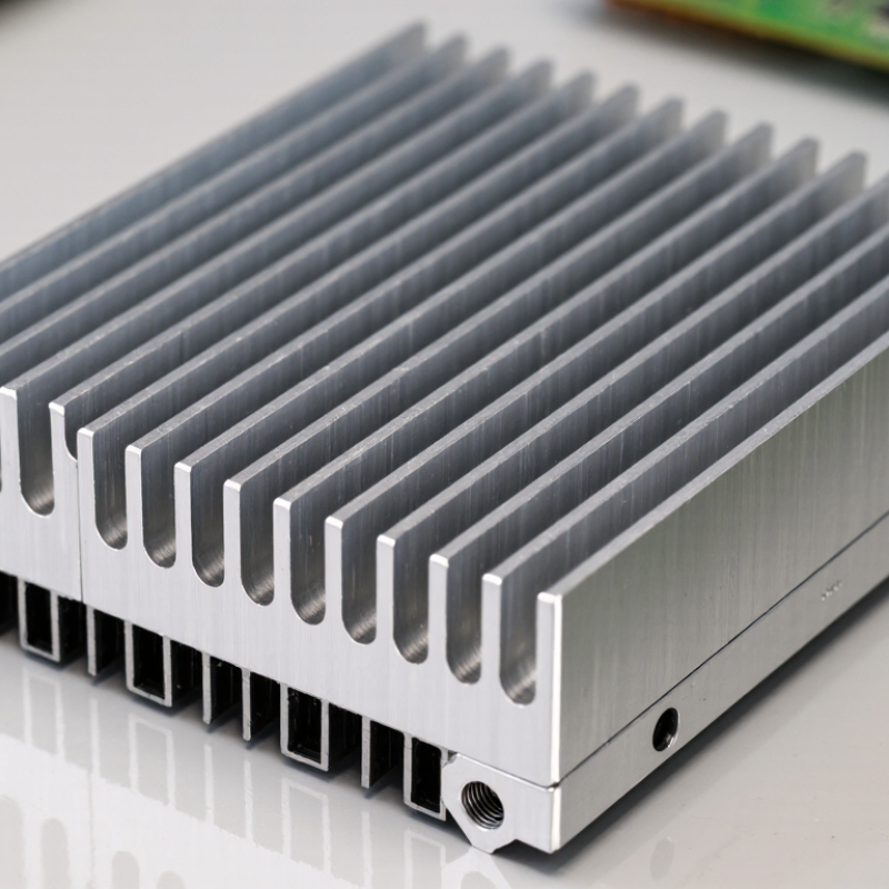
An extruded heat sink starts with heated 6063 aluminum, pushed through a shaped die. This process creates a continuous base and fin structure in one piece. Its thermal conductivity is about 200 W/m·K, allowing heat to move efficiently from an electronic component into the fins. The result is a practical balance of performance, weight, and manufacturing cost.
The aluminum profile can be cut to specific lengths for power modules, LED assemblies, and compact control equipment. Deep fins increase surface area, while open channels support natural or forced airflow. In real thermal design, this detail matters. A crowded enclosure can reduce cooling performance, even when the material conducts heat well. Contact resistance matters too. A flat base, suitable thermal interface material, and firm mounting pressure help transfer heat into the sink.
The number is useful, but not magical. 6063 aluminum may conduct near 200 W/m·K, yet the complete assembly can perform poorly with weak airflow or poor contact. Designers should check heat load, ambient temperature, fin spacing, and orientation together. A thicker profile may improve spreading, but it also adds weight and material use. Sometimes, a simpler extrusion works better. Testing a prototype with a thermocouple can reveal temperature differences that calculations miss. Small design assumptions deserve another look.
Why Choose an Extruded Heat Sink?
Extruded heat sinks commonly use 6063 aluminum because it combines good thermal conductivity, low density, corrosion resistance, and easy formability. At room temperature, 6063 aluminum conducts heat at approximately 200 W/m·K.
Approximate thermal conductivity values at room temperature. Actual values vary with alloy temper, purity, temperature, and measurement method.
Follow the Extrusion Process: Standard Profiles Reach Approximately 6,000 mm
Why Choose an Extruded Heat Sink?
Follow the Extrusion Process: Standard Profiles Reach Approximately 6,000 mm
An extruded heat sink begins with an aluminium billet, heated and pressed through a shaped die. The process creates continuous fins with consistent spacing and wall thickness. Standard profiles can reach approximately 6,000 mm before cutting, according to common guidance from the Aluminum Extruders Council. This length supports efficient production for LED systems, power supplies, and industrial controllers.
The number matters. Longer runs reduce repeated die starts, handling steps, and material interruptions. The International Aluminium Institute reported global primary aluminium production of about 70 million tonnes in 2023. That scale reflects aluminium’s established industrial supply chain, but material availability does not guarantee perfect thermal performance. Fin height, base thickness, air movement, and mounting pressure still control the result.
In practical production, I would not treat 6,000 mm as an automatic promise. Press capacity, alloy choice, die complexity, straightness, and the cooling table can reduce the usable length. A long profile may also bend slightly during cooling. EN 755 and EN 12020 guidance helps define dimensional expectations, yet drawings should still specify cutting tolerance and flatness. This is where many designs become less certain. A profile that looks efficient on paper may require thicker fins or shorter sections after testing. Small details matter.
Why Choose an Extruded Heat Sink? - Follow the Extrusion Process: Standard Profiles Reach Approximately 6,000 mm
| Extrusion Process Dimension | Typical Data or Range | Why It Matters for Heat Sinks |
| Common material | Aluminum alloys, commonly from the 6000 series | Provides a practical balance of thermal conductivity, strength, corrosion resistance, and extrudability. |
| Standard profile length | Approximately 6,000 mm before cutting | Long extruded lengths support efficient cutting into multiple heat-sink assemblies while reducing joint interfaces. |
| Profile cross-section | Designed around the required base thickness, fin height, fin spacing, and mounting features | The cross-section determines available surface area, airflow paths, mechanical fit, and thermal performance. |
| Heat-transfer surface | Longitudinal fins formed directly during extrusion | Integrated fins eliminate separate fin-to-base joining and provide a continuous thermal path. |
| Typical manufacturing sequence | Billet heating → die extrusion → cooling → straightening → aging → cutting | Each step influences dimensional stability, surface quality, hardness, and final assembly accuracy. |
| Die-function advantage | One custom die can form the base and fins as a single profile | This can reduce component count, secondary joining operations, and potential thermal-interface resistance. |
| Cut-length flexibility | Long profiles can be cut into application-specific lengths | Suitable for power electronics, LED systems, industrial controls, and enclosure cooling requirements. |
| Dimensional control | Controlled according to the applicable aluminum extrusion tolerance standard and drawing requirements | Defined tolerances help ensure reliable mounting, consistent contact pressure, and repeatable assembly. |
| Surface finishing options | As-extruded finish, anodizing, powder coating, or machining after extrusion | Finishing can improve appearance, surface durability, corrosion resistance, or electrical isolation when required. |
| Main selection benefit | Efficient production of continuous, repeatable, application-specific profiles | Extrusion is a strong choice when the design needs integrated fins, scalable production, and profile lengths of approximately 6,000 mm. |
Note: Actual profile length, alloy, tolerances, fin geometry, and finishing specifications depend on the extrusion press, die design, applicable standards, and project requirements.
Assess Thermal Performance Through Fin Density and °C/W Resistance
Why Choose an Extruded Heat Sink?
An extruded heat sink removes heat through a solid aluminum profile with shaped fins. Its thermal performance depends strongly on fin density and °C/W resistance. Fin density describes how closely the fins are spaced. Higher density can increase surface area, but it may also restrict airflow. In natural convection, widely spaced fins often perform better than crowded fins. Forced airflow changes the balance.
Thermal resistance gives a practical comparison. A 2°C/W heat sink with a 30-watt load produces an estimated 60°C temperature rise above ambient. This estimate excludes interface resistance, airflow changes, and mounting errors. I have seen installations fail because designers trusted the catalog value without checking fan direction or enclosure clearance. The number is useful, but never complete.
Tips: Measure the actual air temperature near the heat sink, not across the room. Confirm the fin direction matches the airflow path. Use a thin, even thermal interface layer. Compare °C/W values under similar test conditions. A quick test with a thermocouple can reveal unexpected hotspots. Do not assume more fins always mean better cooling. Sometimes, the “improved” design performs worse in a quiet enclosure. Recheck the result under the highest expected load.
Compare Extrusion with Die-Casting Using ASTM B221 Material Standards
Why Choose an Extruded Heat Sink?
When thermal performance matters, extrusion offers a dependable path from specification to production. ASTM B221/B221M covers aluminum and aluminum-alloy extruded bars, profiles, tubes, and related shapes. It addresses chemical composition, mechanical properties, dimensions, and testing requirements. This gives engineers a clear basis for reviewing alloy and temper choices. In practical thermal design, I often value that traceability. A consistent profile also supports predictable airflow and contact with the mounting surface.
Die-casting is different. It can produce complex shapes, thin walls, ribs, and integrated mounting features in high volumes. However, ASTM B221 is not a general acceptance standard for die-cast components. A B221 certificate cannot validate a die-cast heat sink. Die-cast parts need a suitable casting specification, agreed alloy limits, and process controls. Extrusion may require extra machining, and that cost is easy to underestimate. The comparison is not perfectly neat.
Tips: Confirm the alloy, temper, profile tolerances, and surface requirements before requesting quotations. Ask for test records, not only a material name. Check flatness near the mounting face; a small gap can reduce thermal transfer. For a short, highly complex part, die-casting may be practical. For long, uniform fins, extrusion usually gives stronger control and simpler qualification. Measure the real assembly, too. Drawings can hide difficult interfaces.
Match Heat-Sink Geometry to Loads Above 100 W and Required Airflow
Why Choose an Extruded Heat Sink?
For loads above 100 W, heat-sink geometry must match airflow, not just power. A 100 W device needs 0.20°C/W total thermal resistance for a 20°C temperature rise. That budget includes the interface, heat spreader, and air path. Extruded heat sinks provide continuous fins, predictable conduction, and flexible length selection. They work especially well with steady, directional airflow. Wider fin spacing can reduce pressure drop, while tighter spacing increases surface area. The correct balance depends on fan capacity and enclosure resistance.
ASHRAE Thermal Guidelines emphasize airflow management and temperature control in electronic environments. The Uptime Institute’s Global Data Center Survey also shows that cooling remains a major operational concern. In practical testing, airflow often matters more than adding extra fin length. I once treated a 120 W load with a dense extrusion. The calculated surface area looked sufficient. The fan could not push air through it. The result was disappointing. Geometry must follow the real airflow curve, not a catalog rating.
Tips: Measure airflow at the heat sink, not beside it. Check pressure drop, contact flatness, and interface thickness. Leave space for exhaust air. For forced cooling, begin with moderate fin spacing and validate temperatures under continuous load. Thermal simulations help, but physical testing still exposes mounting errors, dust buildup, and uneven airflow. Small mistakes matter.